Summary
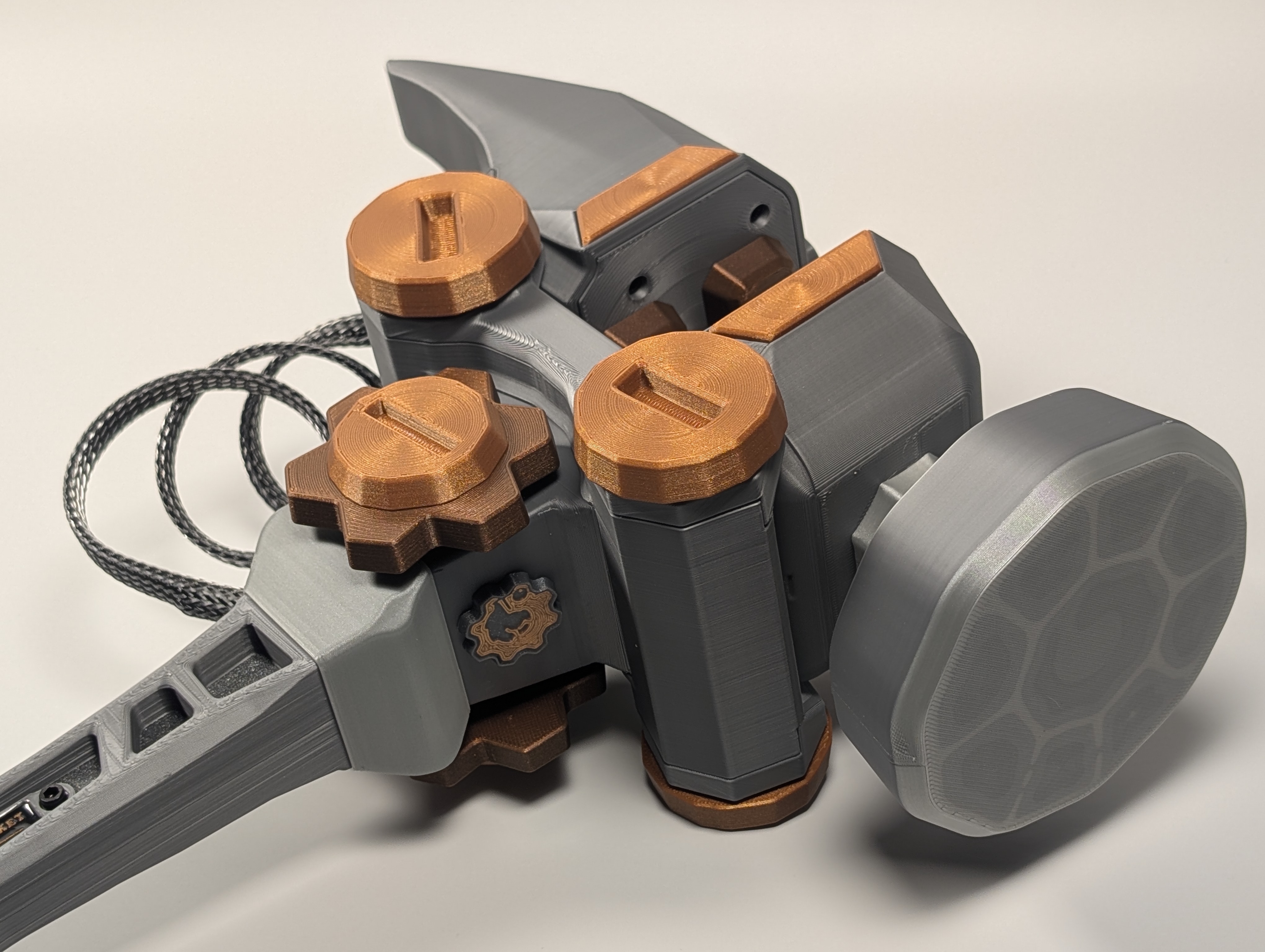
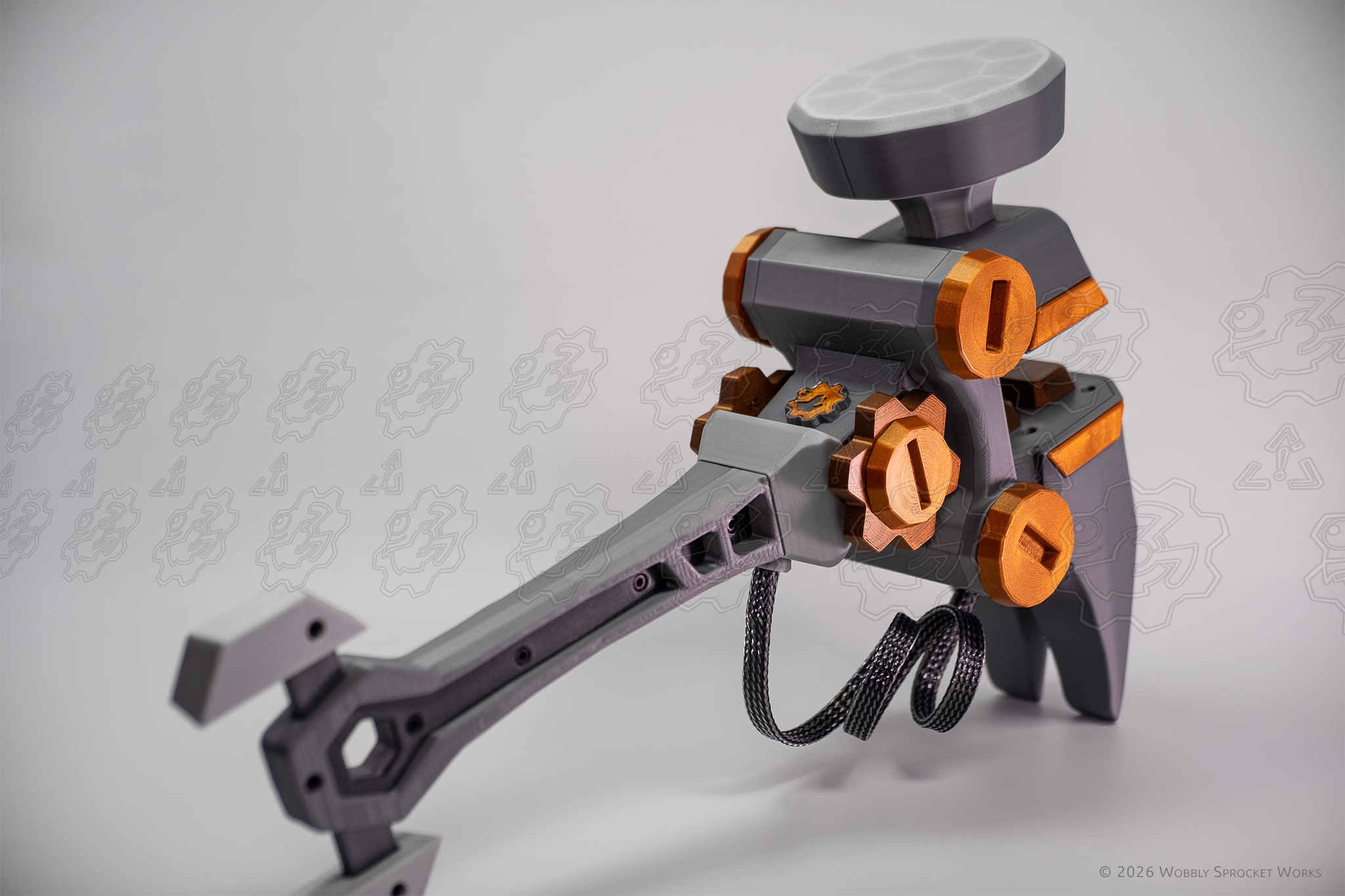
Mechanical cosplay prop inspired by the WoW engineering profession.
Design Origin
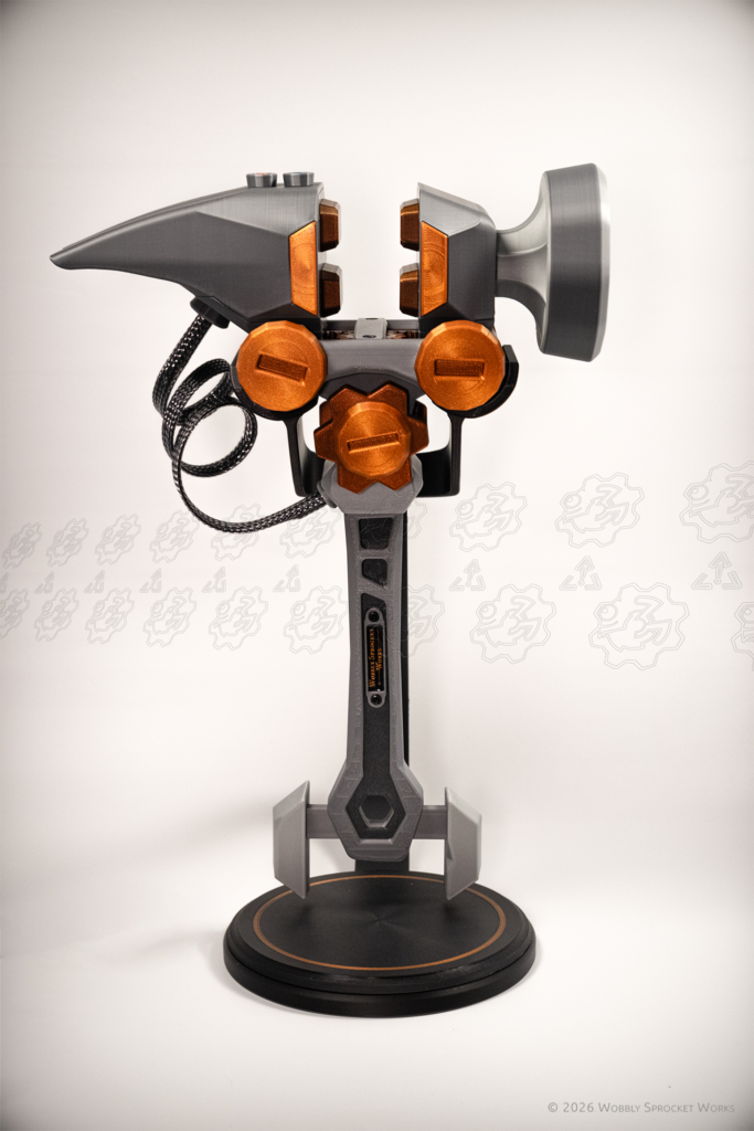
This item is inspired by an in-game crafting tool from World of Warcraft, called a samophlange. The samophlange item is a bit of a running joke which has made appearances here and there in WoW quests since the game first came out. In a more recent expansion, it became an item which appears in your character’s hand when you are practicing the engineering profession. It is a sort of clamp on a stick, with a hammer head and pry bars on either side of the clamp. It has spinning bolts and cogs, and jaws that slide open and shut. See the in-game item 3D preview here on wowhead.com.
Since seeing it in-game, I have wanted one – a REAL one. It appears nobody else felt this way, because I haven’t seen one available to 3D print… so I decided to design it myself.
Note:
I have played WoW off and on since beta. My first character was a troll shaman, and my favorite one is a warlock who has been race changed several times, but is always an engineer. I played the warlock while raiding in a 10 man heroic and mythic raid group during Mists of Pandaria and Warlords of Draenor. Since then my guild has gone our separate ways, but we still keep in touch. I miss WoW once in a while and sign up for the latest expansion until I get bored doing dailies and questing by myself. Besides, I have cool things to be about designing!
Disclaimer:
I don’t want to misrepresent the capabilities of this device. It is intended to look and move like the game item it’s inspired by. It is not intended as any sort of functional clamp, or hammer. The clamping force of this thing is pitiful, and you’ll have an easier time using the magnets in the jaw teeth to grab metal objects, rather than trying to clamp stuff with it. It is an ‘engineer’s tool’ with no real purpose – it’s a clamp on a handle, which is completely pointless. Clamps are intended to fix something in place so it can be worked on. A handle is intended to grab so you can move something around. That is the beauty of the design – it’s pointlessly fun, and I give big props to the artist who came up with the in-game item.
Design Goals
I didn’t make it easy on myself, either – I had some lofty design goals:
- I wanted it to move just like the one in-game.
- It had to be faithful to the in-game item in scale and looks. This was probably the largest challenge. The in-game item’s model has a very low polygon count, meaning it is not very detailed and this left me some work interpreting the shape into something with more detail and actual working physics. This resulted in some bouts of decision fatigue at times. Moreover, fitting a working gear train inside what amounted to a handle was interesting to say the least – especially one capable of moving two big chunky clamp jaws.
- It had to be sturdy – a true cosplay prop that could survive being wielded during a crowded convention for days and come out the other end no worse for wear. Something you could hand to your kids to play with and not worry about them breaking it.
- It had to be completely repairable and moddable. No glue is used in the assembly process – with a couple sizes of hex drivers, you can tear it down to its tiniest parts, replace or modify or paint anything you want, and put it back together again.
- It had to look good. Let me clarify by saying I am usually unimpressed with the quality of typical 3D printed items. No print is perfect – you will always have layer lines and such, but my criteria are: no support marks, visible sagging filament, or messy areas with visible bridges. So, I spent a lot of time figuring out ways to either print the parts nicely, or to hide areas that couldn’t be improved upon due to manufacturing limitations.
Note on model availability:
I spent about 10 months’ worth of full-time hours designing this, with a good chunk of that time spent researching mechanical methods of power transmission, as well as learning a whole lot about the Fusion software and about designing for 3D print.
To give you an idea of the scale of this effort, Fusion increments the version of a model each time you manually save the file. This one is at version 227, and I would generally save once or twice in a round of design that would last anywhere from 4-8 hours.
I have decided not to share this model publicly for a few reasons:
- The amount of design time I put into this was atrocious – I had no idea how much work it would be when I started out. I would like to recoup some of that R&D cost so that I can continue to design things of this nature.
- This build is not for the faint of heart, and attention to detail is important. There are 122 M2 and M3 screws holding it together, and there are numerous places where using the wrong screw length will punch an ugly hole somewhere it shouldn’t be.
- There is also the worry that people might apply too much torque to these screws and strip out the plastic. The assembly uses self-tapping screws because there wasn’t room for heat-set inserts in many places, and they would have added substantial weight anyway.
- The BOM purchase list required is a little more extensive than I think most people are looking for in a printing project. There are non-printed components and related tools and processes involved, such as:
- metal rods which need cutting, shaping and cross-drilling
- ball spring detents of two different spring weights
- 8 different lengths of M2 screws and 7 lengths of M3 screws
- cable sleeving of a particular size
- UV resin is used in a couple of places
- magnets of a certain size, inserted during a printing pause
- adhesive silicone grip pads (cut to size, for the display stand)
My plan for this product is to sell assembled ones via my shop. I am considering the idea of selling kits so that I can lower the cost a bit for folks who would enjoy building their own. I am currently working on writing instructions for the assembly process and I plan to make a build video as well. Even if I don’t end up selling DIY kits, I want those instructions to be available for people who take theirs apart for whatever reason.
Design & Manufacturing Process
I started out with screenshots from wowhead’s model viewer, and used them as a guide for my initial sketches in Fusion. There was a lot of perspective distortion in them, so I ended up eyeballing many things.
I started with the handle and worked my way up to what I ended up calling the gearbox – the portion in between the big cogs on either side. This needed to contain gearing to transmit the turning of the cogs (the user input, if you will) upward through a skinny (about 1 inch square) but gradually widening space and somehow use it to open and shut the clamp jaws, as well as turn the spinny bolts. At that point I panicked, researched, tried some stuff, failed, and repeated until I had something I thought looked viable.
The first method I tried was a comically complex arrangement of spur gears. Some of them, as it turned out, would have needed to be so small that I would have trouble printing them in enough detail for them to actually work.
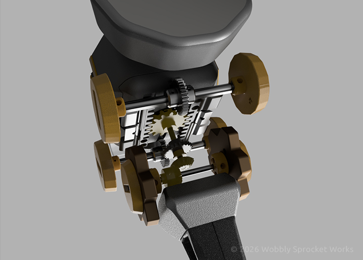
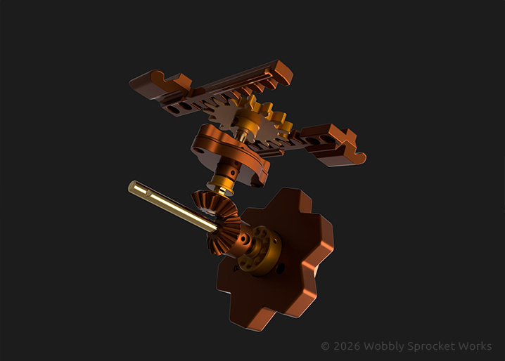
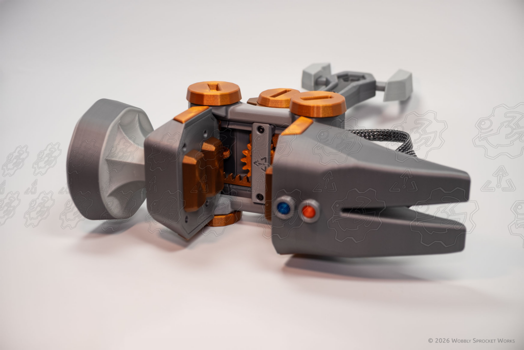
I ended up using bevel gears to transmit the rotation of the cog-knobs 90 degrees. These were attached to a shaft which ran up the middle of the gearbox, capped on top by a spur gear which behaves like the pinion portion of a rack-and-pinion setup. (Like the steering in a car!). The pinion gear drove two racks which were attached to the clamp jaws – this way, they would move in opposite directions which is good for getting a clamp to do clampy things.
So that was several problems solved, and some more to go. I had to get those big ol’ jaws to move freely on one axis up to certain limits, and be held fast on the other axes. In other words, the jaws needed to be able to slide open and shut but not shift side-to-side or fall off, and they needed to be able to do this using the meager torque I could transmit around a 90 degree bend and through a 1 inch hole.
I thought about using bearings so the jaws could roll, or rods on which the jaws could slide, and either of those could probably work, but at the time I didn’t see a way forward because the decorative spinny bolts were positioned at a height that put them very much in the way of the sliding jaws. I had a handful of millimeters to play with, which was not enough room for bearings or rods. I decided to try something entirely 3D printed, and ended up modeling channels along the sides of the jaw track as well as what I dubbed ‘slider skates’ which fit into those channels in such a way that they could be inserted by tilting them, but once affixed to the jaws, they couldn’t come out of the channels and kept the jaws sitting flat.
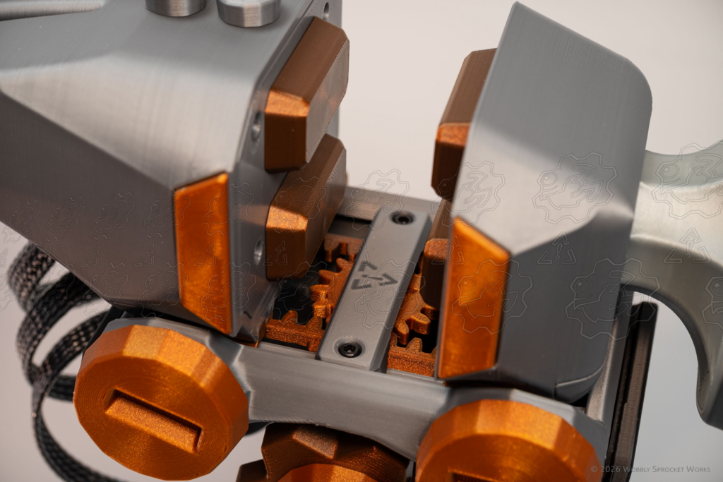
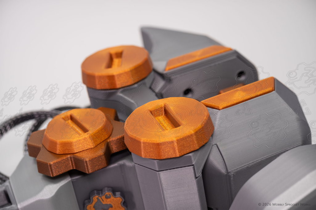
I also had to figure out a way to spin the spinny bolts. This turned out to be pretty straightforward – I modeled another rack-like protrusion onto the bottom of each jaw (on the parts I called the jaw carriages). I gave the spinny bolts a shaft to spin on and a gear which meshed with those carriage racks. As a result, when the jaws moved, they would cause the bolts to spin as well.
At this point I had the handle, gearbox and the bottom portion of the jaws somewhat sorted out, and I exported a gaggle of STL files and started on figuring out whether any of it was printable. After some iterations in Fusion and some experimental prints, I had a prototype and it actually worked pretty well. The slider skates didn’t slide so well at first, but I sanded them and added some lubrication which got the jaw carriages moving nicely. (I later revised the slider skate design to fix those issues and lubrication is no longer needed.) The next hurdle was to see whether this setup would be able to handle the added weight of the jaws (and attached hammer parts) being present on their carriages, but first I had to design them.
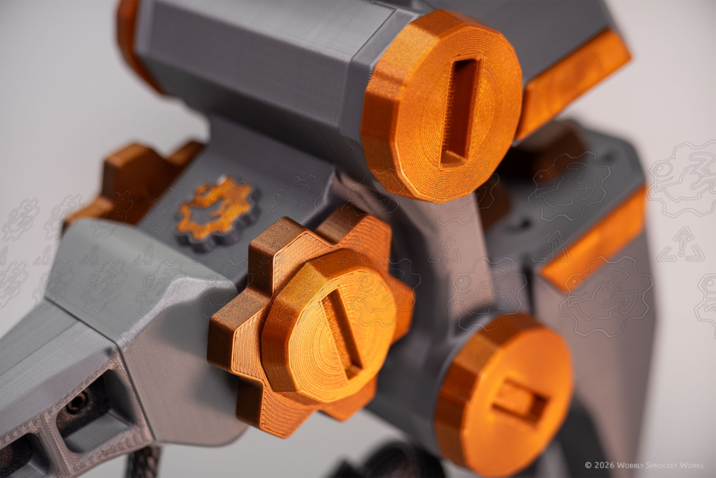
I did a first pass at the jaw upper housings and even managed to include the little trapezoidal decorative parts on the sides, which I was not sure I could print cleanly. The jaw upper housings are hollow but have a nice strong wall count. They attach to the carriages using dovetail joints, so they slide on and then get affixed with screws. The tolerances on those dovetails were a bit tricky – I settled on a fitment that feels too tight at first, but this is due to parallel layer lines rubbing past each other. Once they are ‘broken in’ a little bit, they are snug but pretty easy to remove.
Side Note:
When I mention tolerances, I am talking about designing in a tiny bit of empty space (usually around 0.2 mm) between two parts which need to fit together. Due to several manufacturing phenomena such as elephant foot and x-y hole distortion, 3D printed parts rarely fit together without adding these gaps. A big part of the job of designing an assembly like this is dialing in those tolerances.
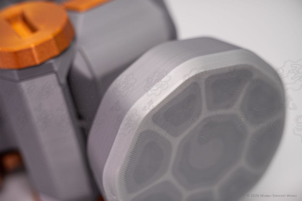
The hammer head is such an outstanding characteristic of this design, so I wanted it to look great and be strong enough to take some beating. It uses hexagonal sparse infill to save on weight, but it boasts 6 wall construction, including on the hammer face itself. I started out with a pretty basic shape and later revisited it to scallop out the ‘stem’ to emulate the way real hammers look. I again revisited it after getting the idea to add a ‘texture’ graphic to the face of the hammer, much the same way a texture graphic gets pasted over a 3D shape in-game. This was done by modeling in separate shapes just under the surface of the hammer face, which were assigned different filament colors in the slicer software. The hammer head is attached with four M3 screws which sink deep into a fully solid-printed section of its stem. This resulted in a very solid feeling.
All that remained to be designed of the upper jaw housings were some covers to close up the hollow housings, and teeth, to provide the bitey bits of the jaws. The only issue I had here was that the first prototype’s teeth would separate a small amount (~1mm) after the jaws were closed. It wasn’t a flaw so much as the result of many small tolerances adding up to a bit of play in the jaws. This bothered me, because a clamp that is closed shouldn’t look a little bit open. I decided to embed magnets in the upper teeth which would attract one another, pulling the teeth closed completely when the jaws were in close proximity. I had to tweak the magnet strength a bit – too strong and it’s a little difficult to get the jaws open again. This was a small change and will probably go unnoticed by many, but to me it seemed like a worthy improvement.
With the upper jaw housings all set, it was time to revisit the issue of whether the gear train could produce enough torque to move the jaws with all the weight present. Up until this point, I’d been using 3D printed shafts for the gear train. To be clear, the filament I am using for this project is PLA pro, and it’s formulated to stretch or bend rather than snapping. So, as I tested the gear train I noticed more and more looseness and play in the knobs before anything would begin to move. It turned out that with the full load applied, the shafts began twisting, rather than rotating, under the stress.
To address that problem, I made the decision to use a more rigid material for the shafts. I was not enthusiastic about using metal, because I didn’t have the tools to drill the required holes in the shafts. So I opted for G10 rods, which are lightweight, strong and easy to cut and shape. However, G10 is made using layers of glass cloth which are soaked in some sort of resin or epoxy and over time it turned out that these rods were prone to splitting under torque, especially when there are holes drilled through them near the ends. I bit the bullet, bought a small drill press and designed some drilling jigs to help me get the holes placed reliably. I used solid brass rods, and they worked out very well.
With the bulk of the design sorted out, it was time to handle smaller details and finishing touches. The cable which runs from the handle to the rear jaw was an interesting challenge – I wanted it to be flexible enough to move with the jaw, but generally keep its shape without needing constant adjustment. I also wanted it to be easily removable for shipping or transport, or in cases where the cable might interfere with someone’s other costume elements.
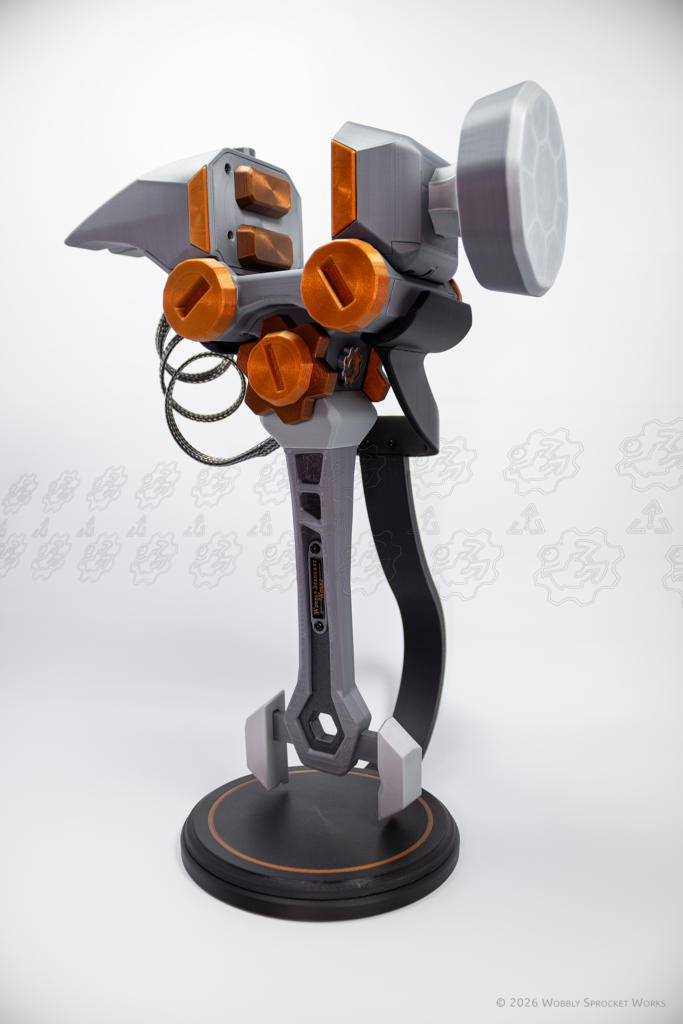
I designed a ‘cable form’ which is printed in a coiled up state, causing it to prefer being that way even after removal from the print bed. There are holes on either end for attaching connectors using screws. I found an open source twist-lock design which was far too large for this use case, so I scaled it down and included it on the cable connectors. I sourced some cool looking cable sleeving and designed a part I called the ‘cable keeper’ which had the job of pulling the sleeving tight and sandwiching it in place between the cable form and the connectors, trapping the sleeving in place. When installed, the coiled cable puts a bit of tension on the lower twist-lock connector in such a way that it is pulled in the ‘tighter’ direction, which does a good job of making sure the cable won’t come loose on accident.
Side Note:
Nearly every part in this assembly was revisited and redesigned at least once, for various reasons. The central gearbox part is the most revised one, and has had about 12 versions.
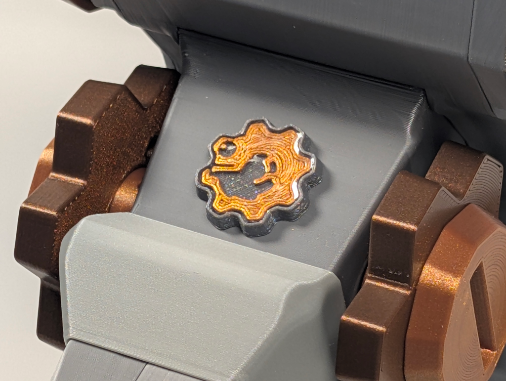
I decided to add a bit of decoration to the handle and gearbox in the form of badges showing my logo and shop name, sort of like they did with antique industrial machines back in the day. I used printed parts and encased them in UV resin to fancy them up a bit. Someday, I’d like to invest in a laser engraver which can handle metal, in which case I will start making these badges that way.
Part of the fun of playing with the Engineer’s Clamp Hammer is the tactile and sound feedback you get when turning the cog-knobs. This was something I had in mind most of the way though the design process, and I tried several methods of making it happen. I knew I wanted detents involved, and I first tried using magnets to cause the knobs to ‘home in’ on certain spots along their travel. The magnets, however, were too small and therefore not strong enough to provide the amount of feedback I was looking for. Next, I tried ball spring detents, which make use of a small ball bearing trapped in a steel tube with a spring behind them. I redesigned the knobs to make use of those, allowing them to drop into small depressions in the knobs for a satisfying click and a notchy feeling.
Another ‘user experience’ issue was that the jaws were sagging a small amount when they were fully open, due to their weight being shifted outward and the racks which move them being made of flexible PLA. It was not very noticeable, but it also came with a bit of rattling when moving the clamp hammer around. To combat this, I added a center brace which fills the gap between the jaws when they are closed. It has geometry designed into its underside which maintains downward pressure on the racks. This encourages the jaws to stay upright and stable when fully open. This is an adjustment/tuning part – on each clamp hammer I’ve built, these have needed a different amount of screw tightening. Too tight, and it becomes hard to get the jaws to move. Too loose and the jaws sag a little when fully open.
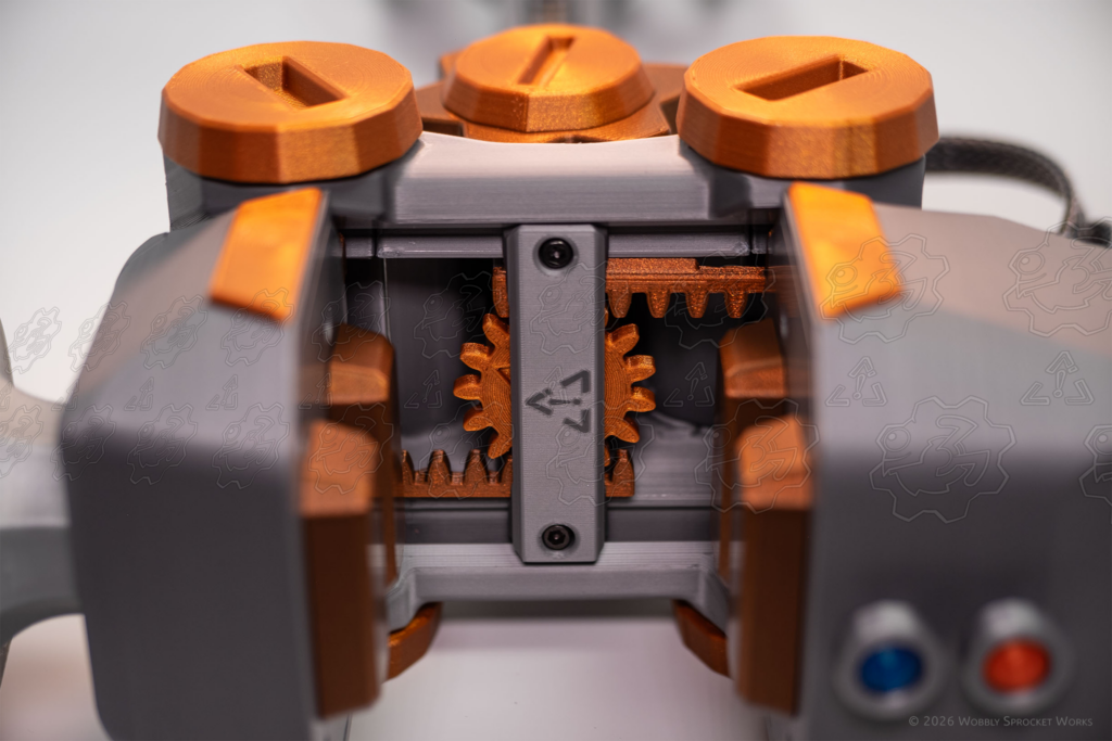
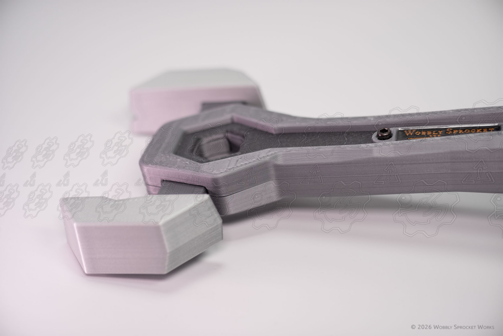
Just when I thought I was just about done with this design, I discovered a bit of a problem. Since I had switched the gear train’s shafts over to brass rods, it was now capable of delivering much more torque – which is great! Unless you happen to be in a situation where the clamp’s jaws are held in place (like when they are all the way open, closed, or clamping down on something) and then you keep turning the cog-knobs anyways. With the new brass shafts, the weakest link in this situation was now the bevel gears. They would grind each other down until they no longer worked, and this could happen pretty quickly.
Now, part of my brain was telling me that surely people would not try to continue turning the knobs when they were clearly being stopped by something. That part of my brain is an idiot and I have learned over the years never to listen to it. People will definitely try to clamp a clamp onto things, even if I tell them it doesn’t really work as a functional clamp. Don’t even get me started on what kids would try with it. As such, this was clearly in violation of my sturdiness requirement, and needed to be addressed.
I knew what I wanted to happen, and I was pretty sure the functionality already existed in the mechanical world. I wanted to add a device which, under normal operation, did nothing. Then, when the torque applied to the gear train rose above a certain threshold, the device would slip, allowing the user to turn the knob as much as they wanted but saving the gear train from damage. When the torque lowered back down, the device would then resume doing nothing. I even had an idea that I could use some more ball spring detents to do this.
It turns out this is a common thing used to prevent gear train damage, and it’s called a torque limiter. They (mechanical engineers) do indeed use ball spring detents to build one type of them, as well. After reading a bit about them, I designed my own. The main issue this introduced was that I would need to chop the vertical gear shaft in half, which makes the resulting two shafts quite small. This was an acceptable tradeoff though, for the peace of mind of knowing this clamp hammer would stand up to all manner of clamp-trigger-happiness. Sturdiness requirement, restored.
I figured this thing could use a display stand, so I designed one which supports the weight nicely. I made the base hollow and it can be opened up for the purpose of adding weight (e.g. ball bearings) for stability, although it works nicely without doing this. The only issue was that the pads on which the clamp hammer perches were a bit slippery, and it could slide off if bumped. To prevent this, I sourced some adhesive silicone grip padding, cut it to shape and added it to those pads, as well as the bottom of the base for good measure.
Testing Process
For testing, I used my original design goals’ sturdiness requirement. I built up a prototype and just began playing with it, and even smashed it into hard surfaces more than a few times. I also knocked it off of varying heights onto a hard floor, sometimes on purpose. The worst that happened was some scuff marks, which disappeared after heating them briefly with a torch (a magic bullet for PLA scuffs). I actuated the knobs about 8 million (estimated and exaggerated but it was a fricken lot) times. I also gave it to my child to play with, but all she wanted to do was beat me up with it, and I am now able to confirm that it’s tougher than I am. Judging by how sturdy this prop is, I would feel confident bringing it with me through a busy convention.
Closing Thoughts
Hopefully, some other WoW nerds out there will be as excited about this design as I am. In the future, I’d like to design more video game inspired props.