
Summary
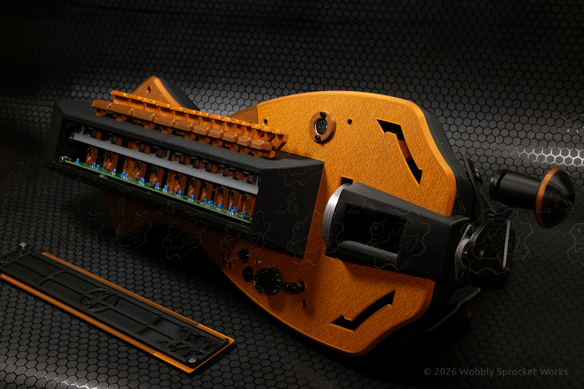
Full body redesign of a MIDI-based hurdy gurdy (musical instrument).
Note:
Links to more info about the hurdy gurdy, as well as the specific models I mention can be found at the bottom of the post.
Design Origin
For those looking to learn to play the hurdy gurdy, there are only a couple of ways to get your hands on an instrument. While the gurdy is experiencing a bit of a surge in attention, there are only a handful of luthiers who build them, nearly all of whom are located overseas. They also generally have years-long waiting lists.. and oh by the way, they will expect you to part with many thousands of dollars.
The only other viable options are a DIY build-a-gurdy kit called the Nerdy Gurdy, which is still pretty expensive and hard to catch in stock, and a MIDI-based gurdy called the Digi-gurdy. Both of these options are made from laser cut plywood and are good enough to learn on.
I have wanted to learn this instrument since the first time I heard one. After some years of deliberation, I decided to purchase a Digi-gurdy, because it can be used with headphones which meant I wouldn’t bother anyone while learning to play. However, I only really wanted the electronic guts of the Digi-gurdy. I wanted to design my own body for it. So, I contacted Mr. John Dingley, creator of the Digi-gurdy and asked if he would be willing to sell me a kit including the electronics so that I could design and 3D print a new body for it.
Fortunately, he was willing to do so even though he normally doesn’t sell kits. I got on the waiting list and patiently waited about 6 months, and then all of a sudden, I needed to design a hurdy gurdy! I was not able to do the design during the 6 month wait because I needed accurate dimensions of all the parts in the kit, so I needed them in my overly excited hands in order to get started.
Purpose / Goals
As previously alluded to, my main purpose here was to be able to learning to play the hurdy gurdy.
My goals for this design were:
- Sturdiness overkill – no creaks or rattles
- True playability, in case I ever get good
- Form and function – looks good, feels good
- All parts had to fit on my 3D printers’ print bed
Design Process
The first step was to decide on a general shape for the body. This is an entirely electronic instrument, so many design features found on traditional gurdies are unnecessary here. I knew I wanted an overall modern aesthetic. However, I also wanted to pay homage to traditional designs.
‘Real’ instruments often carry a sense of classiness that is hard to put in words – a blend of form and function that in many cases has been refined over centuries. I wanted to try to retain a little of that despite making an electronic instrument out of plastic.
I looked at lots of existing gurdy designs, including ones in video games (Sea of Thieves has quite a selection) to get an idea of what I liked. Then I opened a blank file in Photoshop and began playing with shapes. I first landed on an asymmetrical shape reminiscent of an electric guitar, but after spending some time building out the shell in Fusion, I realized it wouldn’t fit on my print bed. I took half of that shell and mirrored it, causing it to then be symmetrical and as a result, just barely small enough to be printable in two chunks.
The body shell consists of two main parts – a bowl-like base which would hold all the internals, and a lid which would act as the top surface of the instrument. On top of that goes the key box, which is where all of the instrument’s keys are mounted and where the main printed circuit board (PCB) lives.
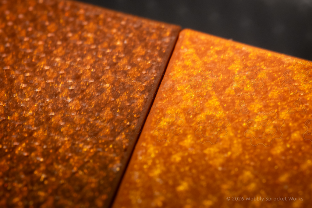
Since I needed to print the body shell in multiple sections so that they would fit on my print bed, I decided to attach them to one another first using zip ties, and then using screws to fasten each panel to supporting pieces which bridged the gaps between parts. This turned out to work extremely well, and resulted in a very sturdy structure.
To explain the zip ties a bit better, when assembling several 3D printed parts which are relatively thin, there is inevitably some flex in them which can sometimes cause trouble when getting everything to line up nicely. The zip ties added some structural rigidity all on their own, but they also acted like built-in helping hands, holding the parts in place while I got the screw holes lined up.
Another way the zip ties were helpful was in spots where I wanted to add some rigidity for aesthetic reasons, in less load bearing areas. For example, where the corners of two panels meet and one sticks out a fraction of a mm further. A zip tie holding those two corners together was enough to even them up, and it was much easier to add two small zip tie loops where there was not enough room to add a screw hole and a boss for the screw to thread into.
All of the zip ties and supporting elements are internal to the body, so they are not visible once the gurdy is assembled. Only the screw heads are visible, so I made sure to give them counter-sunk pockets to keep them looking nice.
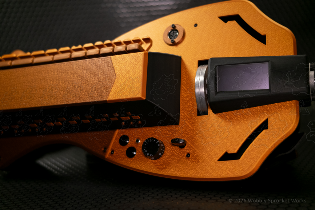
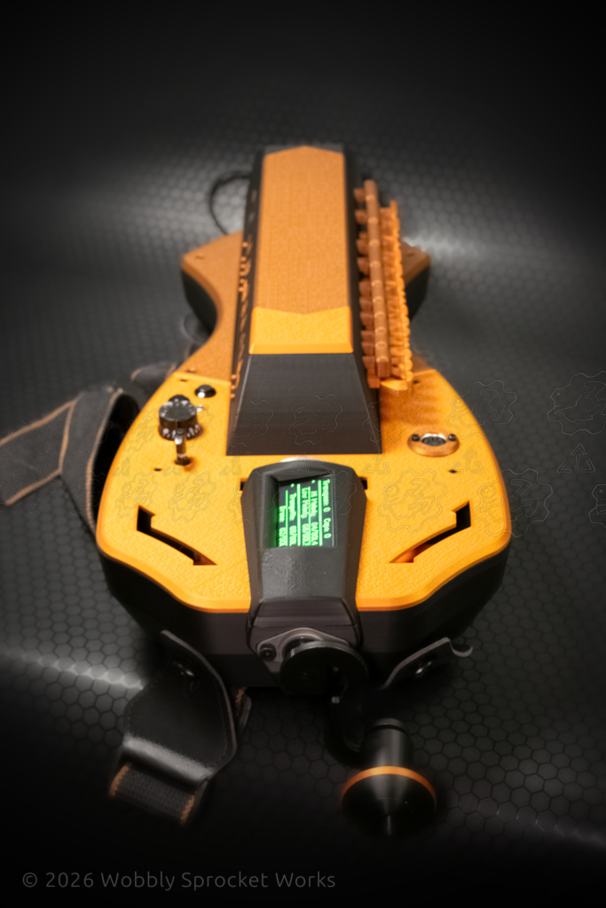
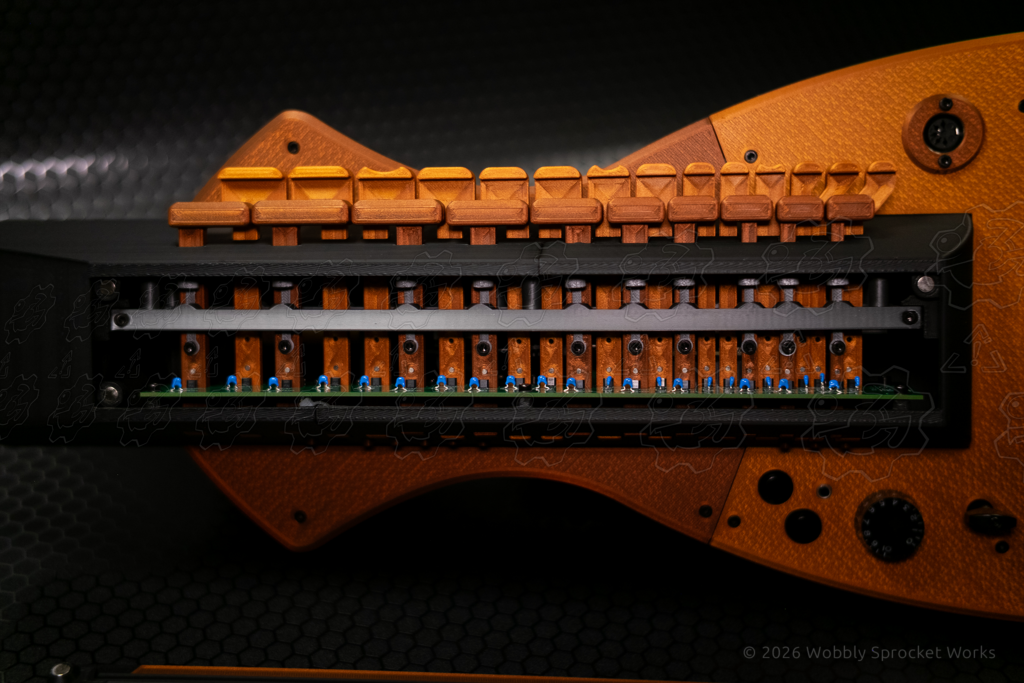
For the key box design, I decided to give it a trapezoidal profile, wider at the bottom than at the top. It also has a subtle curve to the sides, giving it a bit more organic or aerodynamic feel. The ‘head’ of the gurdy, where the tuning pegs would be on a stringed gurdy, is rather featureless and monolithic and bends downward slightly because I am a fan of the gurdy designs which do something similar. The overall shape of the key box and head is something like a bullet train or a futuristic skyscraper perched on top of the body shell and partially embedded into it.
Once the outer shell was roughed out, I needed to add features to it for mounting the internal components, and for physically reinforcing the overall assembly. There were some components I needed to keep in the same place as the original Digi-gurdy design, and so I reproduced the same geometry you’d find inside of it. Examples of this were mounting points for the the main PCB, crankshaft bearings, and the ‘brake shoe’ which provides resistance on the wheel when turning the crank.
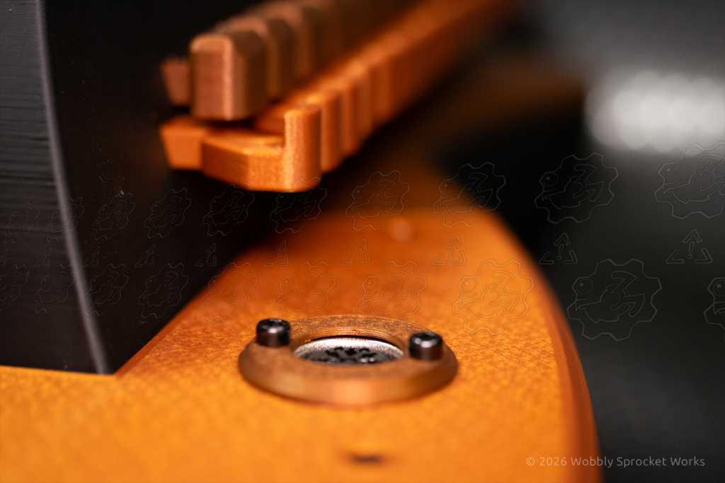
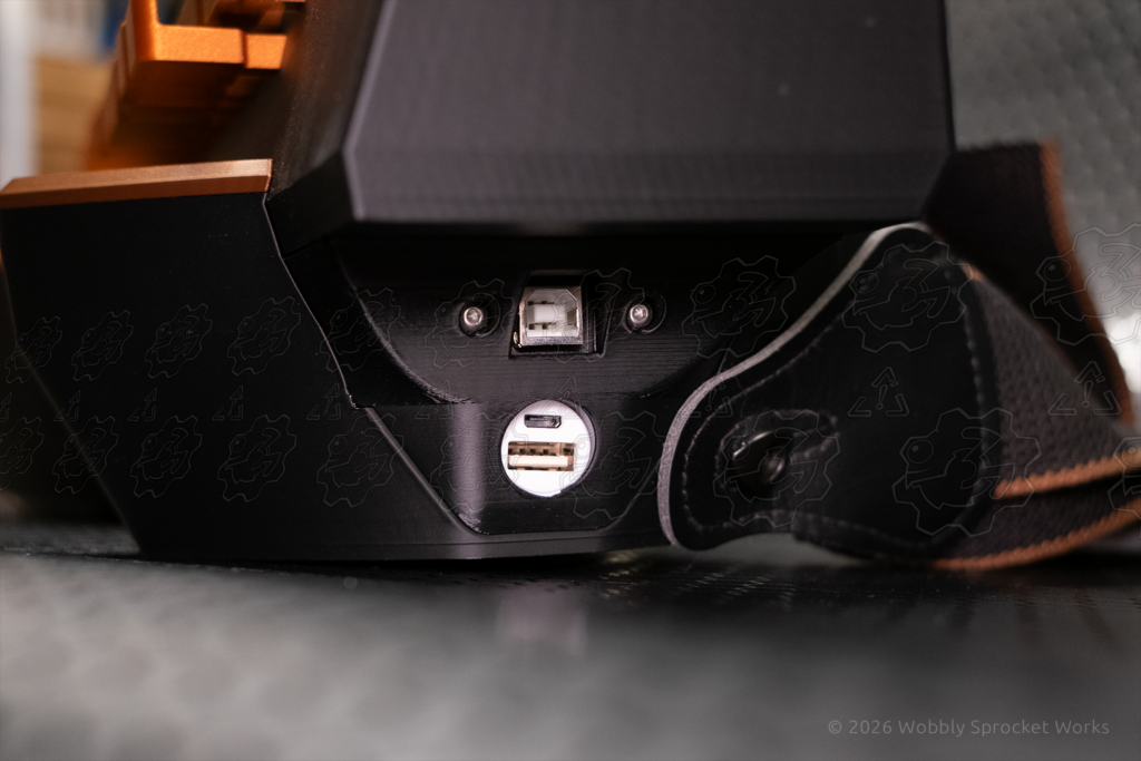
I relocated some other parts entirely, such as the WAV-trigger PCB, the OLED display, and many of the various buttons, connectors and knobs.
The rotary encoder was a mixed case because it remained in the same place as the original DG (Digi-gurdy), but I mounted it to the body’s base below the encoder, whereas the original design mounted it to the key box above.
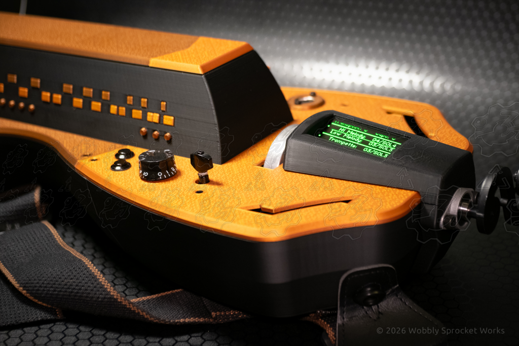

The original DG’s design includes some 3D printed parts. I did not have access to the files for those parts, so I reverse engineered them from measurements. These included the mounts for the brake shoe and rotary encoder, as well as all of the keys. John kindly sent me a set of keys, but since my design widened the key box by a good bit, the provided keys were not long enough. I also ended up adding ergonomic scoop shapes to some of the keys and changing their color, so I would have needed to reverse engineer them anyhow.
The method of returning the keys to position after being pressed was probably my biggest departure from the original DG design, so I will spend some time writing about it. On the stock DG, this is handled using a single tensioned string which the keys press against, providing a feel much like a real stringed gurdy. There is no mechanism to fully return the keys to their resting position – this relies on gravity. For a couple reasons, this bothered me and I wanted a per-key return spring mechanism of some kind.
My reasoning was that I wanted to be able to play this gurdy with it sitting flat on a surface or while I was laying down.. I wanted options, man. Furthermore, when designing with anything possessing a binary on/off state, a return mechanism to a known state is a good idea whether it be an enable pin on an electronic chip, a boolean variable in code, or a physical button. The vast majority of electronic lines carrying digital signals are pulled to a known voltage by default for this reason. I have seen many cases where getting lazy on this detail can cause a lot of grief in the form of intermittent and/or unexpected behavior that can be very difficult to troubleshoot.
The decision to give each key a spring of some kind meant I needed to determine a good mechanism for returning the keys which would fit in a tight space and have a suitable amount of resistance for playing the gurdy (and I had no clue how much resistance that might be).
While I have never designed a musical instrument, I could not help but compare this problem to one I had already thought about quite a bit in the past – PC keyboard key switches. Too little resistance on the keypress would result in accidental presses, while too much would quickly fatigue one’s fingers. (I tend to really jam on my keyboard keys and so I customized all my switches to use a 90g spring, which is on the heavier side for keyboards.)
For the gurdy though, I was only going to be able to customize the spring resistance to a known value if I used metal springs with a known spring rate – and I had another idea I wanted to try out.
When designing the Engineer’s Clamp Hammer, at one point I had a ratcheting component built in which used two opposing magnets as a spring for the button which disengaged the ratchet. I liked the feel and quietness of that mag-spring and I was a bit disappointed when further design changes made the ratcheting mechanism redundant.
As you probably know, when forcing two opposing magnet poles toward one another, the resistance increases as they get closer. This makes for a very smooth keypress and a soft bottom-out feel. Not my favorite for keyboards, but it sounded pretty good for an instrument’s keys – comparable to a piano’s keypress.
The gurdy keys were another opportunity to use mag-springs, and so I jumped in like Leeroy on raid night. I already had 6x2mm cylinder magnets from previous projects (6mm diameter, 2mm thickness), so I decided to try those first. Any larger in diameter and I’d start having trouble making them fit, and I knew they needed to be at least that large based on the weight of the keys, the distance they needed to travel and the friction between the printed parts. I did not calculate this at all – I simply played with the magnets and the printed parts and then made a temporary test rig with a single key to get an idea of where I was at.
I knew from previous research that if I needed the magnets to repel more strongly, I could double or triple them up. For example, using the 6x2mm magnets, I could stack them so that each side was now 6x4mm and the resulting magnetic fields would provide more spring force. This can be done with cylinder magnets until they are the same height as their diameter, and then the strength increase quickly falls off from there. So if needed, I could go up to 6x6mm magnet stacks on each side (if they fit in the space available). This applies to any size of axial cylinder magnets, meaning the magnetic field radiates out from the flat faces. This is the most commonly available type of cylinder magnet, in my experience.
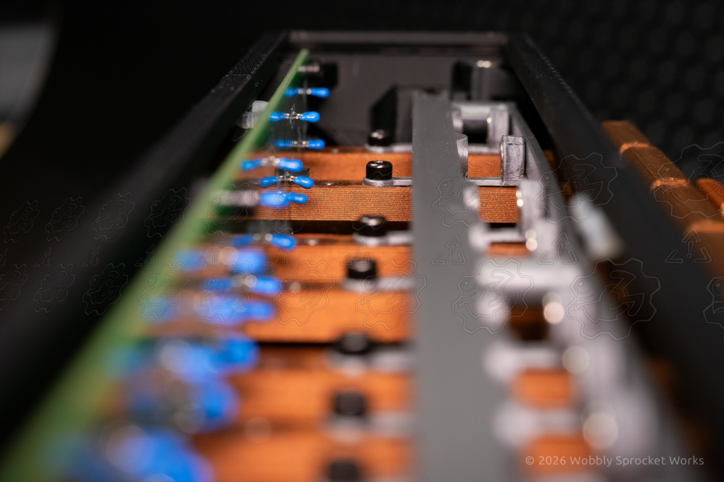
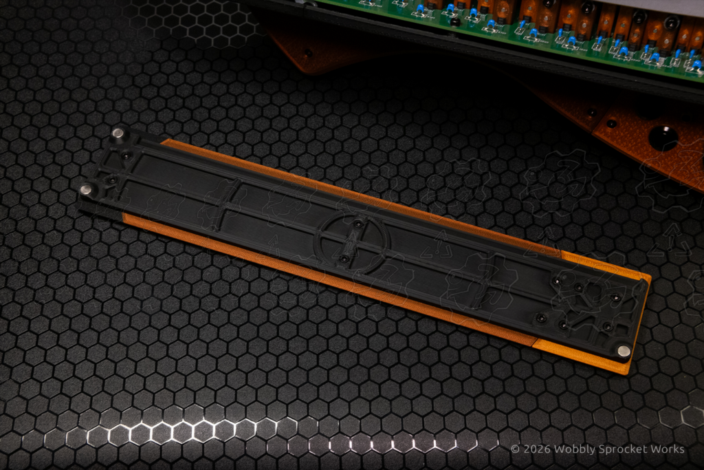
I have already written more about the mag springs than I intended to, so I will just hit the major points from here. I designed a small part to be attached to each key inside the key box which would hold a 6×2 magnet. It resembles a small cup, mounted on its side. This setup is not so different than a real gurdy which uses a part called a tangent attached to each key to press on the string and change its note. I also designed a frame which would hold all of the opposing magnets at the correct distance from those mag-tangents. The frame is designed to be as beefy as possible and is mounted/pulled into the ends of the key box under tension with long screws, so that the keypresses would bend it as little as possible. All of the keys pass through this frame and then through the main PCB, just like the original DG design.
A bit of background on the current Digi-gurdy design: each key contains a really small 2x4mm cylinder magnet, embedded in its stem. When the key is pressed in, this magnet passes underneath a hall effect sensor on the main PCB, one sensor for each key. This is how the DG detects keypresses, and that data is then translated into MIDI data which tells a MIDI device what note to play (along with a bunch of other variables). The WAV trigger PCB inside the gurdy can accept that MIDI data, and using its onboard bank of prerecorded hurdy gurdy notes, play the correct note to a speaker or headphones. Alternatively, the MIDI data can instead be piped out to an external MIDI device which will synthesize the desired note instead. This all happens as close to real-time as possible, which is no small feat for a microcontroller. For that reason, the Digi-gurdy’s brain is a Teensy 4.1 microcontroller, which boasts a processor several times more powerful than the fastest arduino while still being able to utilize arduino code. This makes the Teensy popular among MIDI music hobbyists. As a result, the Teensy forums are a gold mine of information related to MIDI synthesizer designs.
Now I am going to go off on a little tangent (you see what I did there). While testing this setup, I first tried single magnets and they didn’t provide enough return force, so I doubled them up. Then an odd thing happened – a few of the keys still did not have enough return force to make it back to their starting positions. I thought this must be due to some of the 3D printed keys being slightly out of tolerance, so I scraped a bit of material off of their stems and polished them, but the problem persisted. The only other variable involved that I could think of was that the magnets were not of a consistent strength (entirely possible though – these were Chinese amazon magnets).
Then I remembered I had a little card, which I bought probably a decade ago. It’s a laminated card and it contains a special film which allows one to see a cross-section of magnetic fields when they are placed close to it. So, after spending a considerable amount of time tracking that card down, I arduously removed all of the magnets I had installed in my prototype (happily they were not glued) and compared them using the card.
I found that about 10% of the magnets I used were “duds” with a malformed magnetic field which was much smaller and weaker than normal, which would certainly explain why some of my gurdy keys’ mag-springs were underperforming. So I did what any sane person would do – I removed the chances of this ever happening again by testing every single magnet I had in my prototyping parts bin, which was easily in the thousands, since the small ones are commonly sold in packs of hundreds.
I made a test rig (magna-vision-test-o-matic?) of sorts to facilitate this, by taping a known good example of each magnet size being tested to the back of the film card. Then I could easily see whether the magnet I was currently checking was a dud by comparing the magnetic fields. This made the process as mindless as possible, which allowed me to watch/listen to Netflix to keep me sane (…). My cat Evie was really not pleased about my lap being occupied by magnets and stuff during this time, and tried to lay on top of them but I wouldn’t let her. She too must learn that we sometimes suffer for our creations.
With my magnets now QA’d, I moved forward and ultimately ended up buying different 6x2mm magnets which claimed an N52 rating, meaning they were stronger – in the range of ‘don’t be in between these when they grab each other’. This upgrade was due to the doubled-up previous magnets being not quite strong enough in my opinion, and not having enough space to try tripling them. Another reason was that adding more and more magnets was adding more and more weight, which was beginning to add up. All in all, I learned a bunch of lessons about using magnets during this endeavor.
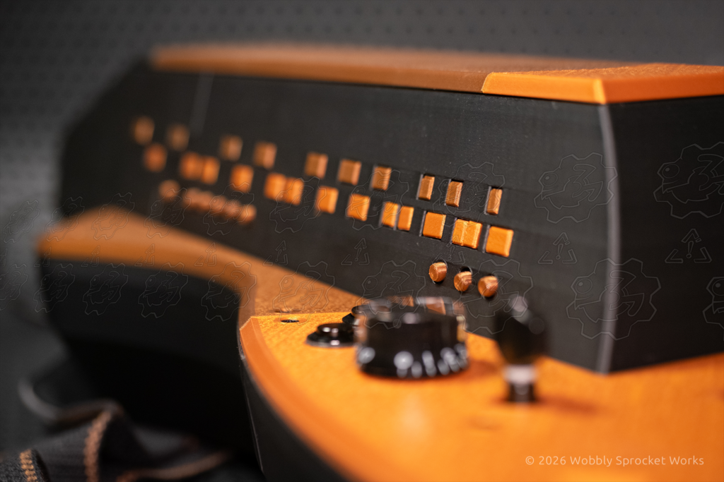
The last major design point I will touch on is the OLED screen. I decided to relocate it to a pseudo tailpiece looking part in the center of the gurdy, because I wanted to add that as a design element while making it functional in some way. I also took the opportunity to tilt the screen toward the viewer so it would be easier to see while playing. This meant it was tilted on 2 axes – one to match the slope of the tailpiece, and another to point the screen toward the eyes of the person playing the gurdy. This was interesting to design because from almost any angle, it just looked crooked and wrong and I just had to trust that it would work when the screen got installed.
Some might notice that the screen on my gurdy is larger than the original – roughly 40% larger and green instead of blue. This is a result of me accidentally breaking the screen which came in my kit – I was installing it and tightened the nut a little too much, which cracked the glass panel of the OLED and killed half the screen. This sort of thing happens sometimes when making. My advice: have spares of fragile things.
I managed to find an exact replacement screen based on pictures, amount of pins and the signal names on them. During my search for that replacement I also found a larger screen with the exact same pinout and signal names, and thought, ‘what are the chances I can just plug that in and it will work’. So I rolled the dice and bought the larger screen too. An $11 risk for a part I can still use elsewhere if it didn’t work out was ok to me.
As it turned out, the larger screen did work, mostly. When displaying text, it wraps down to a new line in one spot where the original screen did not. However this isn’t very noticeable because the only character wrapping to that new line is an equals sign = which looks almost intentional and doesn’t affect the usability. I have since learned that the larger screen is based on a different but very similar chip, so even though the Teensy code is tailored to the smaller screen’s chip, it still works almost perfectly. I could probably change 2 characters in the code and fix that small glitch, which I might do one day.
I really needed to wrap this project up, but someday I might try to hack apart a portable speaker with an aux-in line and build the entire thing into the gurdy’s body, using the speaker’s battery as the gurdy’s power source. This would enable the gurdy to play its own music or output to headphones, and increase battery capacity by a lot in one go.
Manufacturing Process
While the design portion of this project was pretty eventful, the printing and assembly were thankfully not. I didn’t have any major hiccups with print results, my initial part orientations and other slicer settings were adequate for the most part, and my design choices made the assembly mostly painless. The body and key box panels were large and took about 7 hours to print apiece, and I ended up reprinting the body twice due to design iterations.
The only real difficulty arose from the very specific order of operations necessary for assembly, and learning what it needed to be. This was mostly due to the fact that the keys had to be inserted through the key box, mag-tangent frame and main PCB before the mag-tangents could be installed in them. After the key box was essentially completed, it needed to be screwed down onto the body shell – but access to those screw locations was completely blocked by everything I’d just installed in the key box. In the next revision, I relocated those screws to be accessible.
The 2nd revision was more of a personal preference choice – I changed my mind about where to mount the WAV trigger PCB, and since I was reprinting anyhow, I changed a couple of other small details, like adding more internal support for the spots where the strap anchors are installed on the body shell.
In order to accommodate my relocations of various parts, I needed to modify the wiring of the DG to add length. I also took the opportunity to tidy things up a bit, add strain relief where possible and make as many connections as possible use connectors, rather than have the wires soldered directly to the PCB. This was to make assembly easier since I could get everything mounted and then connect up the wiring without worrying about accidentally pulling a wire too hard and doing damage.
To accomplish this I needed to de-solder the wiring, clean the PCB’s pads of the old solder, and then solder header pins onto the pads instead. Most of the pads were spaced at the correct pitch for the header pins I had, and the rest were close enough that I could bend the header pins enough to make them fit. Before starting on each set of wires, I took pictures and drew small schematics in order to ensure I reconnected everything correctly. I also changed almost all the wiring to colored ribbon cabling, and the colors made it easier to document what should be going where without needing to add tape labels to each wire.
For the connectors I added, I used paint markers to color code each connector pair. On the non-polarized ones, I paint marked pin 1 so I could make sure to get the orientation correct, as some of the DG’s components can be damaged by hooking them up backwards.
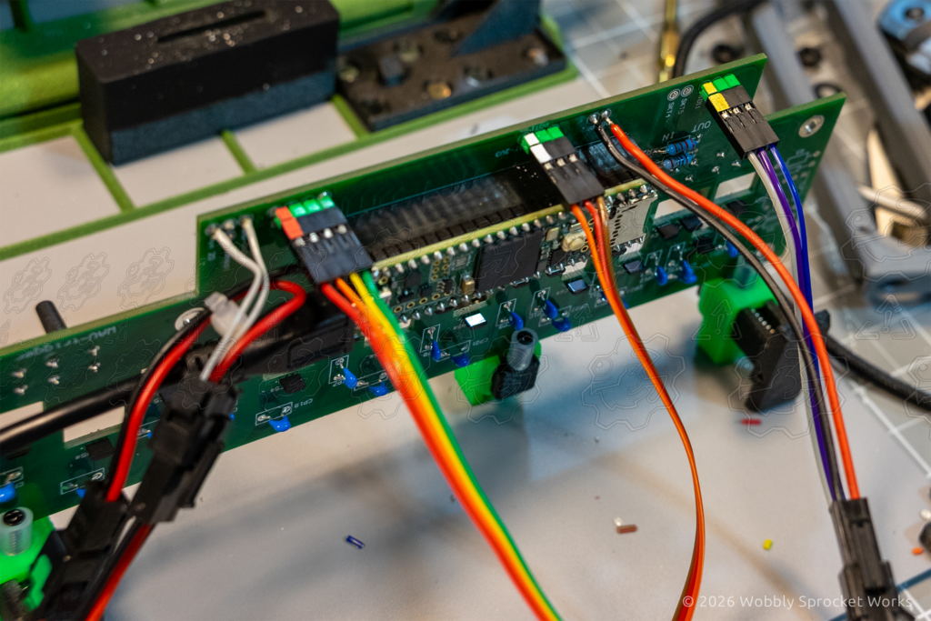

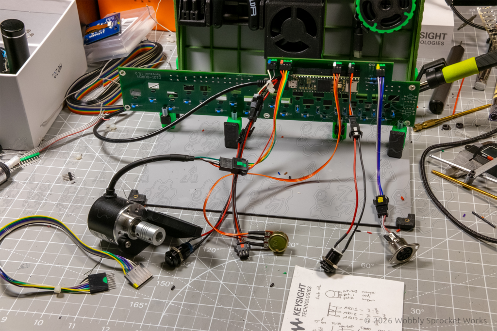
This process was fun, because once upon a time I did very similar work as my day job. I used to spend all day crimping pins onto wires, populating connectors, building cable harnesses and soldering prototype PCB’s. So, this was sort of a “let’s see if I’ve still got it” challenge.
Testing Process
A lot of the testing took place during the design phase, as previously mentioned. Mainly it was the key box I needed to test due to the changes I made there. I set up a single key at first, tested the mag-tangents, and iterated them twice I believe. The first iteration was to adjust for using a single magnet instead of two, stacked. The second one was due to the changes I made to the keys, which changed the dimensions of the mag-tangents a little bit.
Other than that, the testing process is basically just me playing it. If it ever has a problem, I’ll update the design.
Closing Thoughts
Well I don’t want to ‘drone’ on for too long, (that’s a gurdy pun, and it’s bad, and I should feel bad but I do not) so I will wrap this up.
I am a big fan of hurdy gurdy music. This project is near to my heart, and I hope I can play it decently someday.
Check out this video to hear some amazing gurdy music.
Links to more hurdy gurdy info:
Intro and functional explanation: https://gurdyworld.com/gurdyblogs/what-is-the-hurdy-gurdy-a-complete-introduction/
Digi-gurdy:
https://digigurdy.com/
Nerdy Gurdy:
https://www.nerdygurdy.nl/
If you made it this far, thanks for reading!


